Construction of a regulator
To build a controller basically needs to be in possession of evidence of
"handyman", able to identify the electrical / electronic components to be used, patience and attention .
Here you can see the wiring diagram of a three-phase shunt regulator rectifier motorcycle is a simple but effective design, regulated to a fixed voltage of about 13.8 volts, I reckon that's what comes from the factory for major brands and models.
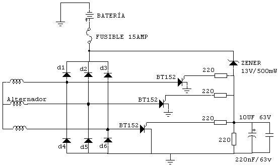
The alternator will generate voltages that are proportional to engine rpm, over 3,000 rpm can easily generate voltage in excess of fifty volts, but our battery only needs 13.8 volts if you apply more tension will die and also a quite scandalous:) the electrical system is affected when the battery is not able to absorb and serve in a protection mode and ... without anesthetic or anything.
If someone makes this show, when you do try it I recommend using the alternator on the bike, of course, but with a separate battery, that way in case of breakdown or accident there is no possibility of damaging the system Electric motorcycle, darling! Components
diodes d1, d2, d3, d4, d5, d6, are integrated into a bridge rectifier at least 35 amps at 400v, the reference at least in Europe is 36MT40
Thyristors are BT 152
all of 220 ohm resistors 1/2w Zener
13 volts 1 / 2 wat
electrolytic capacitor of 10 micros to 63 volts
ceramic capacitor 220 No more than 63 volts
The alternator is already on the bike :)
How does
Some call him rectifier, other regulators, are actually two things or rather the two together.
The rectifier is composed of the rectifier bridge and its function is to rectify the alternating current that gives us the alternator and turn it into direct current that is the kind of tension with our battery works and therefore the vehicle's electrical system The recticador only converts alternating current to continue, if you deliver 50 volts AC is going to convert the 50 volts continuous, and that alone is useless, you also need a regulator that we maintain tension on an appropriate value for the battery.
The controller is composed of three thyristors one for each terminal of the alternator, the thyristors are the real "load burritos" as they are the ones who will
"eating" the excess voltage, the zener diode and other components could be called bone control circuit that tells the thyristors when they have cut excess current to the alternator
This control circuit can be modified to achieve universal unit to provide the charging voltage from 13.6 volts to 14.2 volts.
Deeper: When the voltage exceeds the zener diode thirteen volts and voltage starts to appear in the other leg of the diode, this voltage is applied to it at the gate G of thyristor trigger it going to state Driving
(as a closed switch) and is referred to the negative excess tension. Thus
remains "engaged in this state" because it always repeats the same operation, the tension rises in the diode, has some value when the thyristors begin to cut and well forever. This process occurs continuously and rapidly, thyristors commute very quickly on an inductive load which is the alternator, this can cause the occurrence of transients and harmonics, dangerous to the integrity of semiconductors. Heat is another enemy is deadly for any semiconductor thyristor, transistor or microprocessor of your PC. ALTERNATIVE
Following
a variant of the above circuit is an adjustable control circuit, I've tried on my bike, I know if it responds as in other models, in theory yes. The above circuit
desparace everything except the rectifier and thyristors, add this control circuit that regulates the charging voltage between 13.6 volts and 14.8 volts, I repeat that this has been tested on a virago XV 1100 of 97 and I should respond the same on any bike with an alternator for a shunt regulating system.
